
Uncategorized
How to Calculate the Correct Gas Strut Force (Newtons) for a Toolbox or Canopy Lid
Oct
Fitting a gas strut that is too weak means your toolbox lid slowly sags back down while you are elbow-deep searching for tools. Fitting one that is too strong sends the lid crashing open with enough force to cause serious injury. Getting the Newton rating right is not a matter of guesswork; it is a straightforward engineering calculation that any fabricator can perform before placing an order.
This guide walks you through the complete sizing process for gas struts used on toolbox and canopy lids, covering everything from converting lid weight into Newtons to applying a moment balance formula around the hinge pivot point. You will learn how to locate the centre of gravity, measure your strut mounting positions correctly, and account for the way strut angle and leverage shift across the full opening arc. Two worked examples using real-world steel and aluminium lids illustrate exactly how the numbers come together. The guide also addresses common sizing mistakes, corrosion considerations relevant to Australian conditions, and how to match your calculated force rating to an available strut specification. By the end, you will have the confidence to size gas struts accurately every time.
What You Need Before You Start
Before running any numbers, gather everything listed below. Starting the calculation with incomplete inputs is the most common reason a gas strut arrives under- or over-rated for the job.
Tools to have on hand:
- Bathroom or digital scales (digital preferred for accuracy)
- Tape measure
- Straight edge or plumb line (for locating the centre of gravity)
- Pen and paper or a spreadsheet to record measurements as you go
Weigh the complete lid assembly, not just the panel. Every component that moves with the lid contributes to the load the strut must support. This includes the lid panel, handles, lock cylinders, hinges, any glazing, insulation, rubber seals and internal lining material. A typical handle-and-lock set adds meaningful weight; weigh the complete assembly rather than estimating.
Record distances in metres, not millimetres. You will need two measurements: D, the hinge pivot to centre of gravity, and L, the hinge pivot to the strut mounting point on the lid. The moment balance formula uses metres directly, so converting at source avoids unit errors compounding through each step. For example, 420 mm becomes 0.42 m.
Confirm your strut count now. Strut count is a divisor in the formula; running two struts instead of one roughly halves the Newton rating required per strut. Decide before calculating, not after.
Note your intended opening angle and strut mounting angle. These are not used in the base formula but are essential for the angle correction step that follows. The strut’s effective leverage changes throughout the opening arc, and the worst-case position determines your minimum specification.
Step 1: Convert Total Lid Weight to Newtons
With your scales reading confirmed and all components assembled, the first calculation step converts that mass reading into the unit gas strut force ratings are expressed in: Newtons.
The conversion formula is straightforward:
W (Newtons) = mass (kg) × 9.81
The constant 9.81 m/s² is the standard acceleration due to gravity used universally in gas spring force calculations. Two worked examples that bracket most toolbox applications:
- 8 kg lid: W = 8 × 9.81 = 78.48 N
- 15 kg lid: W = 15 × 9.81 = 147.15 N
These Newton values feed directly into the moment balance formula in Step 4, so accuracy here matters.
As noted in the preparation step, weigh the complete assembly including all planned hardware.
If the lid is not yet fully built, list every planned component, find the manufacturer’s stated weight for each, sum them, and add a small buffer. Erring slightly high protects against undersizing; an underrated strut that sags under load is both a safety issue and a frustration to fix after installation.
Knowing your Newton figure early also helps narrow product selection. Commercial gas struts are available in standard force ratings from 200 N (M3.5 thread) through to 5000 N (M14 thread), so a rough Newton target lets you immediately identify the relevant part of the range before the geometry calculations that follow.
Step 2: Locate the Centre of Gravity
With your Newton figure confirmed, the next input is where that weight effectively acts, the centre of gravity (CoG).
Uniform rectangular lids are straightforward. If the lid is a plain panel with no heavy hardware asymmetry, the CoG sits at the geometric midpoint. Measure half the lid’s depth (front-to-back dimension) from the hinge pivot line and mark that point. That is your CoG for calculation purposes.

Lids with uneven hardware loads require a practical test. Fit all hardware, lock cylinder, handles, seals, then balance the lid horizontally on a narrow edge such as a 19 mm dowel rod. Shift the dowel until the lid neither tips forward nor back. Mark that balance point directly on the lid surface. This is your actual CoG, and it can differ meaningfully from the geometric midpoint when a heavy lock cylinder sits at one end.
Measure Distance D
From the hinge pivot axis (the centreline of the hinge pin, not the hinge leaf edge), measure a straight line to your CoG mark. Record this as D in metres. This distance is the moment arm through which the lid’s weight acts on the hinge.
A larger D means a greater overturning moment, which demands more gas strut force to counterbalance. Repositioning your strut mounting point further from the hinge works in the opposite direction, increasing mechanical advantage and reducing the Newton rating required. These two distances are the core levers in the calculation.
Record D to at least two decimal places, for example, 0.28 m rather than 0.3 m. In heavy-duty canopy applications involving panels above 20 kg, rounding D prematurely compounds through every subsequent step and can push your final result across a standard Newton rating boundary.
Step 3: Measure the Strut Mounting Position
With D recorded, the next measurement is distance L: the straight-line distance in metres from the hinge pivot point to the point where the gas strut attaches to the lid. This is the upper mounting bracket location, typically on the underside face of the lid panel.
L is the mechanical advantage lever arm on the strut side of the equation. The further the mounting point sits from the hinge, the greater the leverage the strut has on the lid, and the lower the Newton rating required to hold it. Conversely, mounting a strut close to the hinge collapses that leverage and forces a significantly higher Newton rating to generate the same holding moment. As a general principle: tripling the distance from the hinge reduces the required strut force to roughly one-third, because the lever arm grows proportionally.
Record L to at least two decimal places (for example, 0.43 m) using the same metre-based units you used for D. Consistent units are essential before applying the formula in Step 4.
Note also the body-side bracket position on the box wall or canopy frame. That lower mounting point does not feed directly into the moment balance formula, but its location relative to the lid bracket determines the strut angle at various positions through the opening arc. You will need both mounting positions for the angle correction in Step 5.
Where fabrication constraints force the lid bracket close to the hinge, such as a bulkhead or internal frame rail limiting your options, the only correct response is to specify a higher Newton-rated strut. Do not attempt to work around poor geometry by other means; the physics will not cooperate.
Gas strut brackets and ball-stud hardware from Trailer Parts Direct are available in configurations suited to both lid-face and box-wall mounting. Selecting the correct bracket type at this stage avoids having to remount hardware after the struts are fitted.
Step 4: Apply the Moment Balance Formula
With W, D, and L measured and recorded, you have everything needed to calculate the required gas strut force.
The core formula, based on torque equilibrium around the hinge pivot, is:
Required Force per Strut (N) = (W × D) / (L × number of struts)
Single-Strut Calculation
Using a 15 kg lid as the example: W = 147.15 N, D = 0.30 m, L = 0.45 m, one strut.
Required Force = (147.15 × 0.30) / (0.45 × 1) = 44.14 / 0.45 = 98.1 N
Round up to the next standard rating: a 100 N strut is the starting point before angle correction.
Dual-Strut Calculation
Same lid, same dimensions, two struts:
Required Force per strut = (147.15 × 0.30) / (0.45 × 2) = 44.14 / 0.90 = 49.0 N per strut
Splitting across two struts nearly halves the rating required from each unit, which opens up a wider selection of standard-range gas struts and reduces stress on each mounting point.
Important Limitation of This Calculation
This formula assumes the strut acts perpendicular to the lid face at exactly 90 degrees. In practice, that condition exists only at one point in the opening arc, if at all. At most lid positions, the strut runs at a shallower angle, which reduces its effective leverage and means the actual force required is higher than this base figure suggests. Step 5 covers how to apply the angle correction.
Always Round Up
Never round down to a lower standard Newton rating. An undersized strut will sag under load, and on heavy-duty gas struts supporting 4WD canopy lids or trade toolboxes, a lid that drops without warning is a genuine safety hazard. Always select the next standard rating above your calculated figure.
Step 5: Account for Strut Angle Throughout the Opening Arc
The base formula from Step 4 assumes the strut acts at 90 degrees to the lid, delivering its full rated force as useful leverage. In practice, the strut angle changes continuously as the lid swings through its travel, and that angle directly controls how much of the strut’s force is actually working against the hinge moment.
The effective moment arm of the strut is L × sin(θ), where θ is the angle between the strut axis and the lid face. When the lid is nearly closed and the strut runs almost parallel to the lid surface, sin(θ) approaches zero. The effective leverage collapses, and the force required to hold position increases sharply. The corrected force at any position is:
Corrected Force = Base Force ÷ sin(θ)
At 30 degrees, sin(30°) = 0.50, so the required force doubles. At 15 degrees, it quadruples.
The exact angle at each position must be determined from your specific mounting geometry; the values used in the worked examples below are illustrative.
Three-Position Check
Rather than solving the full geometry continuously, check three positions:
- Lid fully closed (0 degrees open): strut angle is shallowest, effective leverage is lowest
- Lid at 45 degrees open: mid-travel, moderate leverage
- Lid fully open (90 degrees or more): strut angle is steepest, leverage is at or near maximum
Estimate the strut angle visually or by sketching the geometry at each position, then apply the correction formula. Identify whichever position returns the highest corrected force requirement. That is your worst-case position.
Designing for the Worst Case
The worst-case Newton rating dictates your minimum specification. A strut that holds at its hardest point in the arc will hold at every other point through the travel.
For toolboxes and canopy lids with a standard rear-hinge layout, the worst case is almost always near fully closed. This is also the position where an undersized strut fails first, allowing the lid to drop back onto the user. Size for the closed position, and the rest of the arc takes care of itself.
Worked Example: 15 kg Steel Toolbox Lid with Two Gas Struts
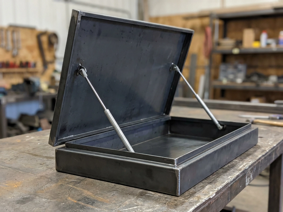
Here is the theory applied to a real build. The scenario: a steel underbody toolbox fitted to an Australian ute tray, rear-hinged, opening to 90 degrees. The complete lid assembly, including two handles and a slam latch, weighs 15 kg.
Step 1: Convert to Newtons
W = 15 × 9.81 = 147.15 N
Steps 2 and 3: Measure the moment arms
Balancing the lid on a straight edge locates the centre of gravity at 0.28 m from the hinge pivot (D = 0.28 m). The strut mounting bracket on the lid face is positioned at 0.42 m from the hinge (L = 0.42 m). Two struts are planned, one per side.
Step 4: Base force calculation at 90 degrees
Required Force per strut = (W × D) / (L × number of struts)
= (147.15 × 0.28) / (0.42 × 2)
= 41.20 / 0.84
= 49.0 N per strut
This result assumes the strut acts perpendicular to the lid, which only holds true at or near fully open. It is not the value to order from.
Step 5: Angle correction at worst-case position
Near the closed position, the effective strut angle is approximately 30 degrees. Applying the sine correction:
Corrected Force = 49.0 / sin(30°) = 49.0 / 0.50 = 98.0 N per strut
Rounding up to the next standard commercial rating gives 100 N per strut. Two 100 N gas struts, one fitted each side, correctly support this lid through the full opening arc without sagging near closed or slamming at full travel.
Worked Example: Aluminium Canopy Lid (Heavy-Duty Application)
A heavier canopy panel pushes the same five-step process into heavy-duty territory, where material selection becomes as important as the Newton rating itself.
Scenario: A 28 kg aluminium lift-up side door on a custom 4WD canopy build, top-hinged, opening outward and upward to 100 degrees, with one gas strut per panel.
Step 1: Weight in Newtons
W = 28 x 9.81 = 274.68 N
At this load, the application sits in territory where heavy-duty gas struts with reinforced seals are typically the better specification from this point forward.
Steps 2 and 3: Moment Arms
- CoG sits at D = 0.35 m from the hinge pivot
- Strut mounts on the panel at L = 0.55 m from the hinge
- One strut per panel (number of struts = 1)
The strut mounting point is well outboard of the CoG, which provides useful mechanical advantage.
Step 4: Base Calculation at 90 Degrees
Required Force = (274.68 x 0.35) / (0.55 x 1) = 96.14 / 0.55 = 174.8 N
This is the force required only if the strut acts at a perfect 90-degree angle to the lid, which it does not near the closed position.
Step 5: Angle Correction at Worst-Case Position
Near closed, the effective strut angle is approximately 25 degrees. Applying the correction:
Corrected Force = 174.8 / sin(25°) = 174.8 / 0.42 = 416.2 N
Round up to the next standard rating: specify a 450 N heavy-duty gas strut per panel.
For a 4WD canopy exposed to Australian conditions, road grime, UV and coastal salt spray, specify stainless steel construction. Confirm that end fittings and mounting brackets are also stainless to avoid accelerated corrosion at the joint.
Common Gas Strut Sizing Mistakes and How to Avoid Them
Even with accurate calculations, a few consistent errors cause most gas strut failures in the field. Recognising them before you order saves rework and prevents safety hazards.
Weighing the lid before all hardware is fitted. As noted in the preparation step, weigh the complete assembly with all hardware fitted; calculating on a bare panel shifts the total Newton load and moves the centre of gravity.
Measuring D from the wrong reference point. The moment arm D must run from the hinge pivot axis, specifically the centreline of the hinge pin, not from the edge of the hinge leaf or the outer face of the lid. Even a 10 mm error here compounds through the formula and produces an incorrect Newton target.
Running a single static calculation. This is the most common reason gas struts hold the lid at 90 degrees open but allow it to drop near the closed position. Effective strut leverage changes continuously through the opening arc; the worst-case angle, typically near closed, dictates the minimum Newton rating. Calculate at three positions and design for the hardest one.
Mounting dual struts at unequal distances from the hinge. If each strut sits at a different L measurement, the load is not split equally between them. Both struts must be positioned symmetrically and each side measured individually to confirm even load sharing.
Selecting undersized struts to reduce cost. An under-rated gas strut will sag under load. Eventually the lid drops without warning, creating a genuine injury risk. Always round up to the next standard Newton rating after applying the angle correction.
Corrosion Considerations for Australian Conditions
Getting the Newton rating right is only part of the specification. Material selection determines how long that rating holds up in service.
Standard gas struts are constructed with a chrome-plated steel rod and a painted or zinc-coated steel body. That construction is adequate for inland workshops, sheltered underbody toolboxes and indoor storage applications where moisture exposure is controlled. It is not adequate for consistent salt spray, tidal environments, or any installation that sees regular high-pressure washing.
When to specify stainless steel
Stainless steel gas struts are available across a wide range of Newton ratings, so there is no force-rating penalty for upgrading the material. Specify stainless steel for:
- Marine trailers and boat storage boxes
- Coastal 4WD canopies and ute toolboxes
- Any application subject to regular high-pressure washing
- Caravan and camper trailer builds where the lid may remain exposed for weeks in remote or coastal locations, even if the home base is not coastal
Matching hardware to the strut specification
Upgrading the strut body without upgrading the fastening hardware creates a new failure point. Mixing stainless steel strut bodies with uncoated mild steel brackets creates a dissimilar-metal pairing that can accelerate corrosion at the joint. Confirm that end fittings and brackets are either stainless steel or marine-grade coated before finalising the specification.
Matching Your Calculated Newton Rating to the Right Gas Strut
With your material selection confirmed, the final step is translating your corrected Newton figure into an actual product specification.
Standard Newton ratings and thread sizes
Round your corrected force figure up to the next standard commercial rating. The progression is 200 N (M3.5 thread), 450 N (M5), 800 N (M8), 1250 N (M8), 2500 N (M10), and 5000 N (M14).
Stroke length
Newton rating alone does not fully define the strut. Stroke length is the second critical specification. Measure the centre-to-centre distance between your two mounting points with the lid fully closed, then measure the same distance with the lid fully open. The difference between those two figures is your required stroke. Order a strut that matches this value exactly; a stroke that is too short will prevent full opening, and one that is too long will put the strut under compression stress at the closed position.
End fitting compatibility
Ball socket, clevis and fixed-eye fittings are not interchangeable. Both ends of the strut must match the bracket hardware at the lid mounting point and the body mounting point. Mismatched end fittings are among the most common installation problems on fabricated toolboxes and canopies, and they are easy to avoid by confirming bracket pin diameter and fitting type before ordering.
Heavy-duty selection criteria
For heavier lids, trade toolboxes in regular daily use, or any geometry where the strut runs at a shallow angle near the closed position, consider heavy-duty gas struts with reinforced seals rather than standard commercial units.
Trailer Parts Direct supplies gas struts and matching bracket hardware across the full Newton range, including stainless steel variants, for toolbox, canopy, caravan, camper trailer and industrial fabrication applications. If your result falls between standard ratings or your geometry is unusual, contact the team to confirm the correct specification before you order.
Quick Reference: Gas Strut Force Calculation Summary
Use this table as a single-page reference once your product selection is confirmed.
| Input / Step | Variable | Formula |
|---|---|---|
| Total lid weight | W (Newtons) | W = mass (kg) x 9.81 |
| Hinge to centre of gravity | D (metres) | Measure from hinge pivot axis |
| Hinge to strut mounting point on lid | L (metres) | Measure from hinge pivot axis |
| Base force per strut | F (Newtons) | F = (W x D) / (L x number of struts) |
| Angle-corrected force | F_corrected (Newtons) | F_corrected = F / sin(strut angle at worst-case position) |
Key rules to apply every time:
- Weigh the complete lid assembly with all hardware fitted before calculating W.
- Measure D and L in metres, not millimetres, to keep units consistent.
- Calculate base force at 90 degrees effective angle first, then apply the sin correction at the shallowest strut angle in the opening arc (typically near closed).
- Always round the corrected force up to the next standard Newton rating. Rounding down produces an undersized strut.
Standard Newton ratings for reference: 200 N, 450 N, 800 N, 1250 N, 2500 N, 5000 N.
Quick example: 15 kg lid, D = 0.28 m, L = 0.42 m, two struts, worst-case strut angle 30 degrees.
- Select: 100 N rated strut (next standard rating above 98.0 N)
Getting the Calculation Right Before You Order
With the formula reference locked in above, the final step is applying it with discipline before you place an order.
Run all five steps in sequence: convert total lid weight to Newtons, locate the centre of gravity, measure both lever arms, apply the moment balance formula, then correct for the worst-case strut angle through the opening arc. Skipping any step introduces error that compounds into a wrong Newton rating.
The risk runs in both directions. An undersized strut sags progressively and eventually drops the lid without warning. An oversized strut slams open with enough force to cause serious injury. Neither failure is acceptable on a working 4WD canopy or trade toolbox. The formula eliminates the guesswork by grounding the selection in geometry rather than estimation.
As a final reminder: weigh the complete lid assembly with every component already fitted, handles, locks, hinges, seals and any lining material, before calculating W. Hardware additions after the calculation shift both the total load and the centre of gravity position.
As a final reminder: run the moment balance at a minimum of three positions through the opening arc, not just at 90 degrees open. The worst-case position, typically near fully closed, sets the minimum Newton rating you must meet.
Trailer Parts Direct stocks gas struts across the full standard Newton range, including heavy-duty options for canopy and high-cycle applications, stainless steel variants for coastal and marine environments, and matching bracket hardware for both lid-face and box-wall mounting.
If your geometry is unusual, your application sits between standard ratings, or you want a second check on your sizing before ordering, contact the Trailer Parts Direct team directly with your measurements. Getting it right before fabrication is faster than correcting it after installation.
Conclusion
Calculating the correct gas strut force comes down to four fundamentals: accurate lid weight, precise centre of gravity location, correct mounting geometry, and checking the moment balance across the full opening arc. Skip or estimate any one of these, and your Newton rating will be off before you even place an order.
Use the formula and worked examples in this guide to run your own calculation with confidence. If your application is non-standard or you want your figures verified before ordering, contact the Trailer Parts Direct team. Getting the sizing right the first time saves time, money, and the genuine safety risk of a lid that fails under load.